
PoE Cable Heating, Bundling and Temperature Derating
Why high-power PoE bundles heat up, how temperature rise eats into your distance budget, and how cable category, bundle size and conductor gauge control the outcome.
Every watt a PoE system loses in the cable becomes heat inside a bundle that may contain dozens of other cables doing the same thing. In small installations this is irrelevant. At Type 3 and Type 4 power levels, in a full 96-cable tray, it becomes the limiting factor on the entire design - and unlike a power budget shortfall, it does not announce itself. It shows up as marginal links, reduced reach and shortened cable life.
Where the Heat Comes From
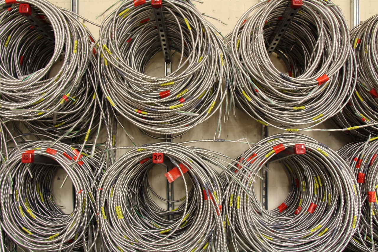
Conductor loss is I²R. Push 600 mA through a pair with roughly 9 Ω of loop resistance over 100 m and you dissipate a few watts along the run. One cable in free air sheds that easily. Put it in the middle of a tightly packed bundle and the heat has to conduct outward through the surrounding cables before it reaches moving air. The centre of a large bundle therefore runs hottest, and it is the cable you cannot inspect.
The Feedback Loop
Copper resistance rises with temperature at roughly 0.4 % per °C. Hotter cable has higher resistance; higher resistance dissipates more power for the same current; more dissipation means more heat. The loop is stable in practice but it steadily erodes margin: a bundle that rises 10 °C adds about 4 % to loop resistance, taking both delivered voltage at the PD and your distance headroom with it.
What Drives Temperature Rise
| Factor | Effect on bundle temperature |
|---|---|
| Bundle size | Dominant. Rise grows sharply beyond about 24 cables |
| Current per cable | Quadratic - Type 4 is far worse than Type 1 |
| Conductor gauge | 23 AWG runs cooler than 24 AWG; 26 AWG patch cord is worst |
| Cable category | Cat6a dissipates better; shielded designs conduct heat outward |
| Ambient temperature | Adds directly to the rise |
| Containment | Conduit and solid trunking trap heat; open basket tray is best |
The Standards Position
The cabling industry addressed this in TIA TSB-184-A and in the corresponding ISO guidance, which give methods for calculating bundle temperature rise and recommend derating the maximum channel length as ambient temperature climbs. The general principle in the cabling standards is that supported distance is reduced above 20 °C, with the penalty accumulating for every degree beyond it. In a plant room at 40 °C carrying Type 4 power in large bundles, the usable channel can fall meaningfully short of 100 m. IEEE 802.3bt was itself written around a bounded temperature rise assumption, which is why the standard's guarantees hold only when the cabling recommendations are respected.
Practical Countermeasures
The cheapest fix is bundle discipline. Keep bundles to 24 cables or fewer where high-power PoE is present, and separate large bundles into several smaller ones with air gaps rather than one dense mass. Use open basket tray in preference to solid trunking or conduit. Where conduit is unavoidable, do not fill it: the same run at half fill is dramatically cooler.
Cable choice is the next lever. Cat6a with 23 AWG conductors has lower resistance per metre and better thermal dissipation than 24 AWG Cat5e, and the difference is worth more at Type 3 and Type 4 than any category-related bandwidth advantage. Shielded constructions help by giving heat a conductive path outward, provided the shield is properly bonded.
Finally, watch patch cords. Stranded 26 AWG or 28 AWG patch cords have substantially higher resistance than solid horizontal cable, and a pair of long thin patch cords at each end can quietly consume a large share of the channel's resistance budget. Keep them short, and specify 24 AWG or better for anything carrying Type 3 or Type 4 power.
Designing With Margin
The pragmatic approach is to treat 100 m as a laboratory figure rather than a design target when high-power PoE is involved. Design horizontal runs to 90 m, keep patch cords short and thick, hold bundles to two dozen, and reserve full-length runs at maximum class for situations where you can control the thermal environment. None of these measures costs anything at design time; all of them are expensive to retrofit once the ceiling is closed.
Need PoE hardware for your project?
Browse our PoE splitters or request a custom power module built to your spec.